Electronics Refresher#
Charged particles exert electric force#
Electric signals in organic tissues are generated by positively charged (Na+, K+, Ca2+) and negatively charged (Cl-) ions. Electrons are the negatively charged particles in our electrodes and wires (i.e., metal) that allow these components to conduct electrical signals.
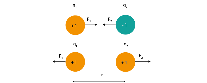
Charged particles exert an electric force on other charged particles.
Equation 1: F = electric force, k = Coulomb constant, q1 + q2 = charges, r = distance of separation.
Coulomb’s law (Eq 1) describes that this force will have both magnitude (it will be bigger if the charges are larger or closer together) and direction (it will either attract or repel, depending on whether the charges have different or the same polarity).
We often represent electric force using electric field lines surrounding the particle. These lines show that charges in the vicinity of the particle will be influenced by its force, and that this influence has a particular direction.
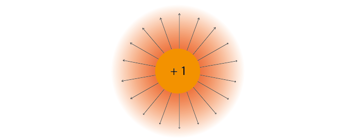
If a charged particle is free to move (for instance, it is an ion in the cytoplasm, and not bound to a membrane) and placed within an electrical field, then these forces acting on it will cause it to move in a certain direction.
Currents are moving charges#
Moving charges create a current (I) measured in Ampere. The current tells us how much charge is moving per second.
By convention, the direction of this current is always the direction of positive charge movement. When we talk about currents generated by a negatively charged ion, such as chloride, we describe it as a positive current moving in the opposite direction to the chloride ion.
Electric Potential Difference#
To create a current of ions across a membrane, we need a driving force to make them move from point A to point B. That driving force is a differences in electric potential. If free to do so, positive charges will move from areas of high potential to areas of lower potential. Just as a difference in gravitational potential energy can cause a river to flow down a mountain, a difference in electric potential can cause charged particles to flow from a region of higher potential towards a region of lower potential until the charges no longer experience a net electrical driving force.
The bigger the difference in electric potential between A and B, the higher the driving force on the charges. If there is no difference in electric potential, no net charges will move (no current). Our driving force is therefore the Electric Potential Difference between two points, measured in Volts and often referred to as ‘voltage’. An electric potential difference (V) is the ability to drive a current (I) from point A to B across a resistance (R).
Figure 3 shows a negative and positive charge that are held in a certain position in space. They are not allowed to move, but still exert an attracting force on each other. If we let them, they would move towards each other.
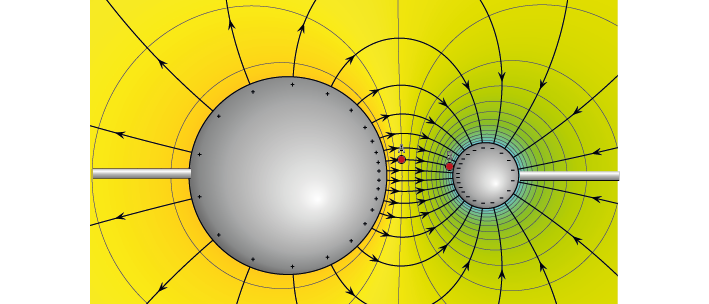
Figure 3: Electric potential mapped around a positive and negative charge.
© 2010 Geek3 /CC BY-SA 4.0, commons.wikimedia.org/wiki/File:VFPt_metal_balls_plusminus_potential%2Bcontour.svg
If we placed a +1 ‘test’ charge at any point in this space, it would experience a net electric force; some influence from the + charge, some influence from the negative charge. The vector description of the magnitude and direction of that force is the electric field, and is shown as field lines on Figure 3.
The electric potential is different to the electric field. While the electric field has both magnitude and direction, the electric potential only has magnitude, and is represented as colour in Figure 3. High, (orange) positive electric potential surrounds our positive charge, and low (blue) negative potential surrounds our negative charge.
If we placed our positive +1 test charge at an area of high potential, like point ‘A’, it would follow the gradient of the electric potential until it reached the negative particle at point ‘B’. The difference in electric potential between point A and B therefore generated a current (a moving charge). We could use that converted potential energy to power something else.
In contrast, to move the same particle from point B to point A, we would need to provide additional energy to counteract the repelling force generated by the positive point charge. The difference in electric potential between two points tells us how much energy we need to move a charge from one place to another. If we were to add more point charges (that are not allowed to move) to this image, their generated forces will sum, giving a more complex map of electric potentials at every point in space.
Because it is defined as a difference between two points, voltage always has to be measured between two points. When we do extracellular recordings, we measure the electric potential difference between the tip of our electrode and our ground or reference point.
Where is 0 volts?#
To describe the height of a mountain, there is no such thing as absolute altitude; instead, we use ‘sea level’ as our point 0 and measure from there. A similar thing goes for voltage. We pick a point to call ‘0 V’ and compare the rest of the circuit to that. This point can be the negative terminal of a battery, the extracellular fluid, or a point at infinity, far from all sources of electric potential (Einevoll et al., 2013).
The terms ‘ground’, ‘reference’, and ‘earth’ are often used interchangeably, but are not quite the same thing.
Reference: A point in the circuit that you labelled 0V, so that you can measure the other values from there.
Ground: Often used as a reference point and considered 0V, but has the additional capacity to provide (source) or get rid of (sink) a lot of current, without its own potential changing.
Earth: The actual earth is the best ground we have. Metal poles in the earth are used to sink current from lightning bolts because the sheer size of the earth means that such a tiny bit of extra current is not a problem, and won’t change the potential of the earth.
Resistance#
Resistance opposes current flow. If you increase the resistance in a circuit without increasing the electric potential difference, current will be reduced.
This is described by Ohm’s law:
Capacitance#
Capacitors for use in electronics are made of two conducting plates, separated by a thin layer of insulating material that prevents the plates from touching. When a capacitor is connected to a voltage source, such as a battery, charges collect on one of the plates. The charges cannot move through the insulating layer, but they can exert a force through it. This electric force pushes away similar charges on the opposite plate. This movement of charge is what gives us current flow in the circuit, even though charges cannot flow directly through the capacitor.
In a direct current circuit, current will flow while the capacitor charges, as charge is pushed or pulled on either plate. Current flow will stop once the capacitor is fully charged. This electric charge can be discharged (and, for instance, used to power something) by providing a path that connects the positive and negative charges of the capacitor.
Impedance#
Unlike a battery, which provides current flow in only one direction, our neuronal currents can move both towards and away from our measuring electrode. Neuronal signals are therefore alternating signals. The frequency of an alternating signal tells us how often the direction of flow changes. The power supply in buildings is also alternating: the current direction switches at a fixed frequency, producing a sinewave (the notorious 50/60Hz noise in ephys recordings).
In alternating signal cases, we need to use impedance (Z) to describe opposition to current flow, instead of using resistance. The impedance represents opposition to current flow measured in both magnitude and phase, which allows us to describe the relationship between voltage and current for time-varying signals. We can measure the impedance of a component at different frequencies, so that we understand both the magnitude and phase relationship between V and I over a broad frequency range (from 1 Hz to 10 kHz). Let’s examine the response of resistors and capacitors to an applied sinusoidal voltage (an alternating signal).
Impedance: Resistors#
For resistors, the impedance magnitude (Z) is constant and does not vary with the frequency of signal applied. The impedance follows Ohm’s Law (V = IR), which doesn’t take the frequency of the signal into account.
Impedance: Capacitors#
In contrast, for a capacitor, the current is 90° out of phase with the voltage, and the magnitude of impedance decreases as the frequency increases. We can therefore only describe the impedance of a capacitor at a certain frequency.