Mapping Channels#
This page is about how we find out which channel of incoming data in our software corresponds to which electrode in a multi-channel setup. It’s easy to assume that tetrode 1A or the tip of your silicon probe must correspond to recorded channel 1, but this is not usually the case. It’s important to double-check this ‘mapping’ so that you can be sure about which depth or area your data is coming from, which channels are noisy or faulty, or which tetrode needs adjusting in depth.

(Looking for Open Ephys Pinouts and Channel maps? They are here!)
Making your channel map#
To build this map, we will have to follow the conducting trace from the electrode (tetrode tip or pad on a silicon probe) through the acquisition system to our software. We can do this using ‘pinout’ maps or charts, which describe which pin in a connector correspond to what function or channel.
To make a channel map, you will need:
The pinout of your probe or electrode interface board
The pinout of the headstage you use
To know the indexing used by your software. The Open Ephys GUI counts channels as 1,2,3,4. Bonsai will count channels starting from 0 (so 0,1,2,3)
Example mapping#
Let’s say you were using an Intan RHD 32-channel headstage (part #C3324) and the Open Ephys Omnetics 32-channel Shuttledrive EIB, and you wanted to know which channels in the Open Ephys GUI corresponded to Tetrode 1 (marked in orange on the EIB below).
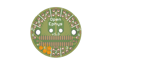
You would start at the EIB pinout diagram below. You can follow the EIB trace to find that tetrode 1 A-D corresponds to P5,P7,P9 and P11 on the Omnetics connector.

Next, we need to find which pins on the headstage will be connected to P5,P7,P9 and P11 on the EIB.
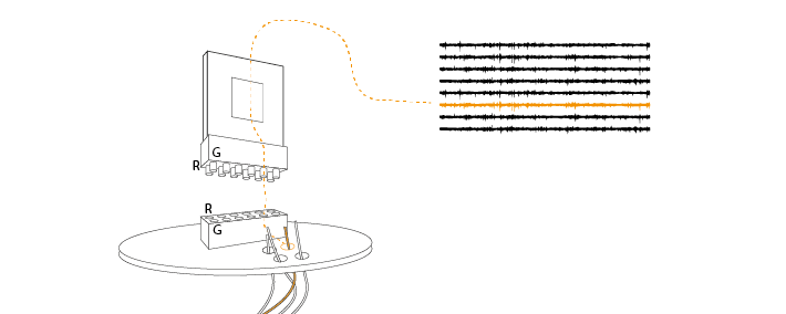
When you connect the headstage, ground (G) and reference (R) on the headstage must contact the ground and reference pins on the EIB. Use these points to make sure you have the correct orientation of your headstage and EIB relative to each other.
You can then use the pinout of your headstage to find the relationship between the Omnetics pins and the channel numbers that the headstage will output:

The Intan headstage will output tetrode 1A-D as 22, 21, 20, 19 (again we have already done this for you for this specific case here) ).
If you were reading this data into the Open Ephys GUI, which starts at 1, you would see that these are channels 23, 22, 21 and 20. You can use the channel map plugin to organise your channels so that, for instance, channels from the same tetrode are grouped together. Save your channel map for next time.

Here is the same setup with our tetrode 1 highlighted, but read into Bonsai, which starts at 0:

Testing a Map#
Making channel maps can be tricky, and it is always worth double-checking you’ve got it right.
On an empty EIB, you can use a wire to, in turn, connect each tetrode hole in the EIB to the ground on the EIB. If you monitor this on the Open Ephys GUI, you should see that channel signal go flat. Use this to test that your channel map is correct.
This does not work with silicon probes, but you could try submerging them slowly into saline. If channels in the GUI have been correctly ordered by depth along the silicon probe, you should see the effect of the saline progressively spread across channels as the probe is lowered.